Begin typing your search above and press return to search. Press Esc to cancel.

ESP8266 ESP-01 WiFi IOT Module Arduino IDE Compatible Overview

ESP8266 is a low cost WiFi chip with full TCP/IP stack and microcontroller capability produced by Shanghai-based Chinese manufacturer. ESP-01 is one of ESP8266 version. This WiFi module allow microcontrollers to access WiFi network.

ESP8266 is a low cost WiFi chip with full TCP/IP stack and microcontroller capability produced by Shanghai-based Chinese manufacturer, Espressif system. This chip become widely available when third-party manufacture, Ai-Thinker started the production on August 2014. During that time, most of the documentation is not in english. This chip become famous due to very low price as compared to another WiFi enable module. 

In late 2014, Espressif released software development kit (SDK) which allow chip to be programmed without the needed of external microcontroller. Since that Espressif has been releasing the latest SDK with two version which is RTOS and NON-OS sdk. Besides that, there are a few another open source SDK instead of the original one. They are NodeMCU (Lua based firmware), Arduino (allow to be programmed as normal Arduino board), and MicroPython (Pyhton for embedded devices).

ESP-01 is one of ESP8266 version. This WiFi module allow microcontrollers to access WiFi network.

ESP8266 ESP-01 (Top View)

With a built-in PCB antenna, this ESP-01 module become more flexible in term of size. Prototype development using this ESP-01 become more portable and compact without the big antenna.

ESP8266 ESP-01 (Bottom view)

There are 8 pins available in this ESP-01 including VCC and GND. Only two GPIO available in this ESP-01 series. 

ESP8266 ESP-01 Pinout

ESP8266 is a complete and self-contained WiFi network solutions that can carry software applications or through another application processor. ESP8266 specifically for mobile devices, wearable electronics and networking applications design and make the machine to achieve the lowest energy consumption, together with several other patented technology. This energy-efficient construction in three modes: active mode, sleep mode and deep sleep mode type.

Below if an overview video of ESP-01. 


Overview of ESP8266 ESP-01 Module


Features: 
802.11 b/g/n
Wi-Fi Direct P2P, soft-AP
Integrated TCP/IP protocol stack
Integrated TR switch, LNA, power amplifier and matching network
Integrated PLLs, regulators, DCXO and power management units
+19.5dBm output power in 802.11b mode
Integrated low power 32-bit CPU could be used as application processor
SDIO 1.1/2.0, SPI, UART
STBC, 1×1 MIMO, 2×1 MIMO
A-MPDU & A-MSDU aggregation & 0.4ms guard interval
Voltage: 1.8-3.8V
Dimension:25 x 15 mm
Net weight:2 g


SUBSCRIBE Youtube Channel for more Tutorial Videos:
Read more ...

NodeMCU V2 ESP8266 WiFi IOT Arduino IDE Compatible Overview

NodeMCU V2 also known as NodeMCU v1.0 is the 2nd revision of NodeMCU series. This WiFi Internet of Things (IOT) module is compatible with Arduino IDE. The default mod for this ESP8266 ESP-12 chip is Ai-Thinker firmware.

NodeMCU V2 also known as NodeMCU v1.0 is the 2nd revision of NodeMCU series. This WiFi Internet of Things (IOT) module is compatible with Arduino IDE. The default mod for this ESP8266 ESP-12E chip is Ai-Thinker firmware. One of the main different between NodeMCU V1 and NodeMCU V2 is the chip was upgraded from ESP-12 to ESP-12E. The board in this version also become narrower compare as before which is a bit wider.

ESP8266 is high integration wireless SOCs, designed for space and power constrained mobile platform designers. It provides unsurpassed ability to embed Wi-Fi capabilities within other systems, or to function as a standalone application, with the lowest cost, and minimal space requirement.

The default baudrate for this NodeMCU V2 firmware is 9600 as shown in figure below.

Back view of NodeMCU V2 / NodeMCU v1.0

Top view of NodeMCU V2 / NodeMCU v1.0

The main reason of this revision become narrower is to allow the board fixed nicely into a breadboard. There are still one row of breadboard left after NodeMCU V2 being stacked. This extra row allow wire jumpers to be connected using a single breadboard only. 

Alternately, serving as a Wi-Fi adapter, wireless internet access can be added to any micro controllerbased design with simple connectivity (SPI/SDIO or I2C/UART interface). ESP8266EX is among the most integrated WiFi chip in the industry; it integrates the antenna switches, RF balun, power amplifier, low noise receive amplifier, filters, power management modules, it requires minimal external circuitry and the entire solution, including front-end module, is designed to occupy minimal PCB area.


NodeMCU V2 / NodeMCU v1.0 Pins

NodeMCU V2 / NodeMCU v1.0 Pinout (Board view)


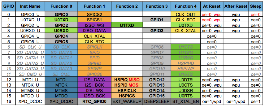
Table below shows the standard GPIO table for ESP8266. Both ESP-12 and ESP-12E is quite similar but somehow there is an extra of 6 GPIO pins in ESP-12E. This ESP-12E (ESP8266EX) is embedded with an enhanced version of Tensilica L106 Diamond series 32-bit micro controller (MCU) which features extra low power consumption and 16-bit RSIC. The CPU clock speed is 80MHz which also can reach a maximum value of 160MHz. ESP-12E is often integrated with external sensors and other specific devices through its GPIO.

ESP8266EX WiFi SoC is embedded with memory controller, including SRAM and ROM. MCU can visit the memory units through iBus, dBus, and AHB interfaces. All memory units can be visited upon request, while a memory arbiter will decide the running sequence according to the time when these requests are received by the processor.

This module is mounted with an 4 MB external SPI flash to store user programs. If larger definable storage space is required, a SPI flash with larger memory size is preferred. Theoretically speaking, up to 16 MB memory capacity can be supported.


ESP8266 GPIO Table

Below is an overview video of NodeMCU V2.


Overview of NodeMCU V2 ESP8266 Arduino IDE Compatible

Features: 
The wireless SoC has the following:
802.11 b/g/n protocol
Wi-Fi 2.4 GHz, support WPA/WPA2
Integrated 10-bit ADC
Integrated TCP/IP protocol stack -ipv4 only at the moment
Integrated TR switch, balun, LNA, power amplifier and matching network Integrated PLL, regulators, and power management units
+20dBm output power in 802.11b mode
Supports antenna diversity
Integrated low power 32-bit MCU

The 32-bit MCU has the following:
GPIO, I2C, ADC, SPI, PWM and many more
Running at 80MHz
64KBytes of instruction RAM
96KBytes of data RAM
64KBytes boot ROM
4MB of flash
RISC architecture


SUBSCRIBE Youtube Channel for more Tutorial Videos:
Read more ...

NodeMCU V1 ESP8266 WiFi IOT Arduino IDE Compatible Overview

NodeMCU V1 also known as NodeMCU v0.9 is the 1st revision of NodeMCU series. Based on Lua script programming, this WiFi Internet of Things (IOT) module is also compatible with Arduino IDE. This module utilizes ESP8266 ESP-12 chip which is a 32 bit microcontroller unit (MCU).

NodeMCU V1 also known as NodeMCU v0.9 is the 1st revision of NodeMCU series. Based on Lua script programming, this WiFi Internet of Things (IOT) module is also compatible with Arduino IDE. This module utilizes ESP8266 ESP-12 chip which is a 32 bit microcontroller unit (MCU). 


NodeMCU was created shortly after the release of ESP8266 chip by Espressif. NodeMCU was started on 13 October 2014 when Hong uploaded the first file of NodeMCU firmware to GitHub. Later on many makers contributed to this NodeMCU community. The most important update is when Devsaurus ported to NodeMCU project on Jan 2015. This contribution enable NodeMCU to easily communicate with LCD, screen, OLED and VGA.

Back view of NodeMCU V1 / NodeMCU v0.9

Front view of NodeMCU V1 / NodeMCU v0.9


ESP-12 consist of 16 pin which then routed to be used in NodeMCU V1. Figure below show the pins of NodeMCU v0.9 or NodeMCU V1. By default, there are 17 GPIO pins whereby only a few of them are usable.

NodeMCU V1 / NodeMCU v0.9 Pins

The integration of ESP-12 into NodeMCU platform allow easier application of this IoT module to integrate with various sensors and display module. Programming become easier since there is no need to use FTDI adapter because users just need to plug in USB only.

NodeMCU V1 /NodeMCU v0.9 Pinout (Board view)

The default GPIO table for all ESP8266 module is shown below. Each GPIO can be configured into different function.


ESP8266 Default GPIO Table

Below is an overview video of NodeMCU V1. The specification of this IoT module is summarized together below the embed video.


Overview of NodeMCU V1 ESP8266 Arduino IDE Compatible


Features: 
The wireless SoC has the following:
802.11 b/g/n protocol
Wi-Fi 2.4 GHz, support WPA/WPA2
Integrated 10-bit ADC
Integrated TCP/IP protocol stack -ipv4 only at the moment-
Integrated TR switch, balun, LNA, power amplifier and matching network Integrated PLL, regulators, and power management units
+20dBm output power in 802.11b mode
Supports antenna diversity
Deep sleep power <10uA, Power down leakage current < 5uA
Integrated low power 32-bit MCU

The 32-bit MCU has the following:
GPIO, I2C, ADC, SPI, PWM and many more
Running at 80MHz
64KBytes of instruction RAM
96KBytes of data RAM
64KBytes boot ROM
4MB of flash
RISC architecture


SUBSCRIBE Youtube Channel for more Tutorial Videos:
Read more ...

How to increase input voltage using XL6009 Adjustable Step Up Voltage Booster DC to DC

In order to use 3.7 V lithium ion battery as a main power source of microcontroller board that require a at least 5V input voltage, an adjustable step up voltage booster DC to DC module is require. The most well known booster module is XL6009 module. This module able to increase input voltage ranging from 3.2V to 30V dc and produce an output ranging from 5V to 35V dc.

In order to use 3.7 V lithium ion battery as a main power source of microcontroller board that require a at least 5V input voltage, an adjustable step up voltage booster DC to DC module is require. The most well known booster module is XL6009 module. This module able to increase input voltage ranging from 3.2V to 30V dc and produce an output ranging from 5V to 35V dc. 

The key principle on how booster work is the tendency of inductor to overcome the change of current and destroy the magnetic field. The buck boost converter is a type of DC-DC converter that has greater output voltage or less than the input voltage. In this tutorial, the step-up buck boost converter is used to increase the small input voltage to a higher output voltage.

XL6009 DC-DC Step-up Voltage Booster Module
3.7V 650mAh Lithium Ion Battery

Figures above show the main components that will be used in this tutorial. We will increase 3.7V of battery up to 30V. User can adjust the voltage based on your own requirement. Video below show the step on how to connect battery and adjust the resistor of DC-DC module in order to increase the output voltage.


How to increase input voltage using XL6009 Adjustable Step Up Voltage Booster DC to DC

Steps: 
1. Connect positive and negative input of XL6009 module with 3.7 V lithium ion battery.
2. Connect the output of XL6009 module with multimeter.
3. Adjust variable resistor on XL6009 module.

Features: 
Input voltage range: 3.2 to 30Vdc.
Output voltage range: 5 to 35Vdc.
Output rated current: 2A.
Output maximum current: 3A (need to add heat sink).
Conversion efficiency: 94%.
Switching frequency: 400kHz.
Dimension: 41 x 20 x 14 mm.
Weight: 12g

SUBSCRIBE Youtube Channel for more Tutorial Videos:

Read more ...