Begin typing your search above and press return to search. Press Esc to cancel.

Showing posts with label arduino. Show all posts

Arduino LED Blinking Tutorial 2

This is tutorial 2 for Arduino. Readers will learn on how to program LED blinking using Digital Pin of Arduino UNO.

This is tutorial 2 for Arduino. Readers will learn on how to program LED blinking using Digital Pin of Arduino UNO. In this tutorial, Pin 12 of digital I/O will be used as an output. There are already built-in LED Pin 13 in this board. But in this tutorial we will use external LED and connects with digital Pin of Arduino UNO.


1. Prepare all the components:

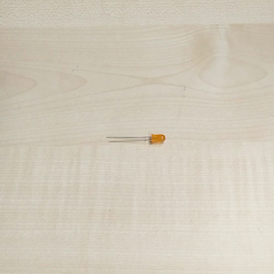
Before we start with the tutorial, you need to prepare all the require components. You will need Arduino Uno board, breadboard, 1K Ohm resistor, LED, USB cable and laptop. Below is all the items required in this tutorial.
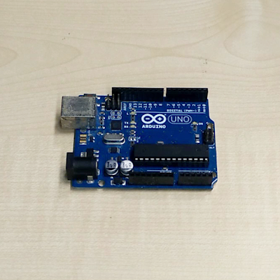

Arduino Uno Board
Breadboard
1k ohm Resistor
LED
USB cable
Laptop


2. Draw a schematics:

Now will all components prepared, we will draw a schematic so that we will refer to this connection before we connect them.


LED Blinking Tutorial Schematic


3. Connects all components:

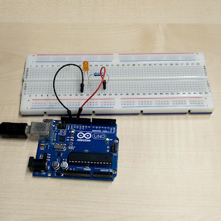
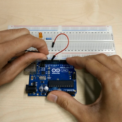
We will connect GND Pin and Pin 12 of Arduino to breadboard. GND pin will be connect to negative pin of LED while Pin 12 will connect with resistor. Resistor will connect with positive Pin of LED.


Connecting all components for LED blinking tutorial.


4. Program Arduino with LED blinking interval of 1 second:

Now, let's write the first code. The first code is to make LED blink with 1 second interval. Arduino will send HIGH signal to Pin 12 with 1000 ms delay and then LOW signal to Pin 12 with 1000 ms. This code will continuously run as they are in the Void loop.

Arduino code for LED blinkin with 1s interval

LED blinking demo with 1s interval (Turn ON)
LED blinking demo with 1s interval (Turn OFF)


5. Program Arduino with LED blinking interval of 0.2 second (faster):

Now, let's write the second code. We will modified previous code to make it blinks faster. Delay value of 1000 is changed to 200.
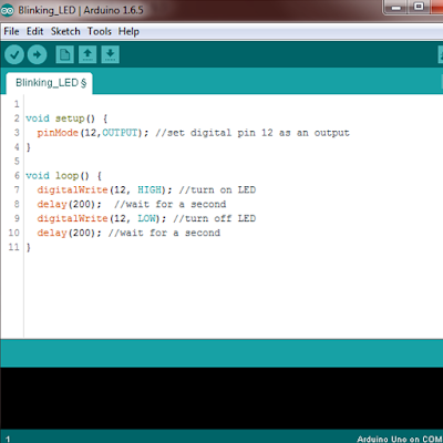
Arduino code for LED blinkin with 0.2s interval
LED blinking demo with 0.2s interval (Turn ON)
LED blinking demo with 0.2s interval (Turn OFF)

DONE!


Below is video tutorial for this LED blinking.


Arduino LED blinking or blink led tutorial projects Part 2


Steps:
1. Prepare all components
2. Draw a schematic
3. Connect all components
4. Program Arduino with LED blinking interval of 1 second
5. Program Arduino with LED blinking interval of 0.2 second

SUBSCRIBE Youtube Channel for more Tutorial Videos:
Read more ...

Arduino Tutorial for Beginners Getting Started Part 1

This is the first tutorial for Arduino. You will learn on how to download and install Arduino IDE.

This is the first tutorial for Arduino. You will learn on how to download and install Arduino IDE. The latest installer also has include together with firmware installation. Before this, it require you to install firmware manually.


Arduino Tutorial for Beginners and Getting started with Arduino
Arduino Tutorial Part 1: Getting Started with Installation and Blinking LED


Steps:
1. Download Arduino IDE from Arduino website 
2. Install Arduino IDE
3. Plug in Arduino and try it with your first code


SUBSCRIBE Youtube Channel for more Tutorial Videos:
Read more ...

Arduino Uno R3 Board Overview

Arduino Uno is a microcontroller board based on the ATmega328P. It has 14 pins of digital input or output pin where only 7 of them can be used as a pulse width modulation (PWM) output. There are also 6 analog input pin available for analog purpose.

Arduino Uno is a microcontroller board based on the ATmega328P. It has 14 pins of digital input or output pin where only 7 of them can be used as a pulse width modulation (PWM) output. There are also 6 analog input pin available for analog purpose. The Arduino Uno can be powered via the USB connection or with an external power supply. The power source is selected automatically. Operating voltage of this Arduino Uno is 5V with input voltage ranging from 6-20V as a power source.

The Arduino Uno differs from all preceding boards as it does not use the FTDI USB-to-serial driver chip. Instead, it features the Atmega16U2 (Atmega8U2 up to version R2) programmed as a USB-to-serial converter. 

The Arduino Uno has a number of facilities for communicating with a computer, another Arduino, or other microcontrollers. The ATmega328 provides UART TTL (5V) serial communication, which is available on digital pins 0 (RX) and 1 (TX). An ATmega16U2 on the board channels this serial communication over USB and appears as a virtual com port to software on the computer. The 16U2 firmware uses the standard USB COM drivers, and no external driver is needed.

Arduino Uno R3 (Top view)

Arduino Uno R3 (Bottom view)

The Arduino Uno has a resettable polyfuse that protects your computer's USB ports from shorts and overcurrent. Although most computers provide their own internal protection, the fuse provides an extra layer of protection. If more than 500 mA is applied to the USB port, the fuse will automatically break the connection until the short or overload is removed.

The maximum length and width of the Uno PCB are 2.7 and 2.1 inches respectively, with the USB connector and power jack extending beyond the former dimension. Four screw holes allow the board to be attached to a surface or case. Note that the distance between digital pins 7 and 8 is 160 mil (0.16"), not an even multiple of the 100 mil spacing of the other pins. 


Input and Output Pins of Arduino Uno R3:


Each of the 14 digital pins on the Uno can be used as an input or output, using pinMode(),
digitalWrite(), and digitalRead() functions. They operate at 5 volts. Each pin can provide or receive a maximum of 40 mA and has an internal pull-up resistor (disconnected by default) of 20-50 kOhms. In addition, some pins have specialized functions:

  1. Serial: 0 (RX) and 1 (TX). Used to receive (RX) and transmit (TX) TTL serial data. These pins are connected to the corresponding pins of the ATmega8U2 USB-to-TTL Serial chip.
  2. External Interrupts: 2 and 3. These pins can be configured to trigger an interrupt on a low value, a rising or falling edge, or a change in value. See the attachInterrupt() function for details.
  3. PWM: 3, 5, 6, 9, 10, and 11. Provide 8-bit PWM output with the analogWrite() function. 
  4. SPI: 10 (SS), 11 (MOSI), 12 (MISO), 13 (SCK). These pins support SPI communication using the SPI library.
  5. LED: 13. There is a built-in LED connected to digital pin 13. When the pin is HIGH value, the LED is on, when the pin is LOW, it's off.


The Uno has 6 analog inputs, labeled A0 through A5, each of which provide 10 bits of resolution (i.e. 1024 different values). By default they measure from ground to 5 volts, though is it possible to change the upper end of their range using the AREF pin and the analogReference() function. Additionally, some pins have specialized functionality:

  1. TWI: A4 or SDA pin and A5 or SCL pin. Support TWI communication using the Wire library.


There are a couple of other pins on the board:

  1. AREF. Reference voltage for the analog inputs. Used with analogReference().
  2. Reset. Bring this line LOW to reset the microcontroller. Typically used to add a reset button to shields which block the one on the board. 


Below is an overview video of Arduino Uno R3.


Overview of Arduino UNO board

Features:
Microcontroller: ATmega328
Operating Voltage: 5V
Input Voltage recommended: 7-12V
Input Voltage limits: 6-20V
Digital I/O Pins: 14 - of which 6 provide PWM output
Analog Input Pins: 6
DC Current per I/O Pin: 40 mA
DC Current for 3.3V Pin: 50 mA
Flash Memory: 32 KB ATmega328 of which 0.5 KB used by bootloader
SRAM: 2 KB - ATmega328
EEPROM: 1 KB (ATmega328)
Clock Speed: 16 MHz


SUBSCRIBE Youtube Channel for more Tutorial Videos:
Read more ...